The Volume Ratio Gas Addition System, DC55
Åke Larsson, Stockholm, Sweden, 8th of January 2002
If you need more info or want to comment the text please contact the author at ake.l@home.se.
Some introductory comments
This document describes the gas addition system of the DC55, a French Semi-Closed rebreather made by Spirotechnique in the 1960’s.
Detailed pictures of the DC55 can be found at Diver Daves’ DC55 tear down page, http://www.nobubblediving.com/dc-55.htm.
The DC55 seems to be manufactured by Aqualung (www.aqualung.com) in a modern version (DC55-97), check the http://www.aquanaut.com.au/Prod/Military/Breath/dc.html.
Note that the fresh gas addition system of the DC55 and the Dr Buchalys’ Halcyon 80 (http://www.halcyon.net/rebreather/index.shtml) are very similar but the original Halcyon PVRBASC works in a different way.
The following text is written under the assumption that the reader has knowledge about the relation between gas fractions and partial pressures as well as basic knowledge in rebreather design. Also, nitrox concepts like MOD and EAD are assumed to be familiar to the reader.
Contents
Some introductory comments........................................................................................... 1
Some Physiology.............................................................................................................. 2
Some DC55 Semi Closed Rebreather Related
Theory...................................................... 2
The DC55 breathing circuit............................................................................................... 3
Fresh gas addition............................................................................................................ 4
DC55 fresh gas addition theory........................................................................................ 4
Duration........................................................................................................................... 6
Some Concluding Remarks.............................................................................................. 6
Some Physiology
In a human body in steady state of work, i.e. during aerobic working conditions, the relationship between the minute ventilation, VE (the sum of tidal volumes over a minute, sometimes denoted RMV), and oxygen uptake, VO2, is about constant. The ratio of minute ventilation and oxygen uptake is often called the extraction ratio, here denoted KE.
 Eq. A
Eq. A
The extraction ratio falls in the range 17 to 25 with a normal value of 20 for healthy humans, the variations primarily depends on the diet of the diver and the dead space of the diver and his equipment.
For more details see the The Interspiro DCSC page */
Some DC55 Semi Closed Rebreather Related Theory
In a semi closed rebreather the oxygen fraction in the breathing circuit, FO2, depends on the diver's oxygen uptake, VO2, and the dumped flow, Qvent, and fresh gas composition, Fmix, of the fresh gas as expressed in the equation below.
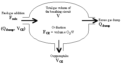
Figure 1. A simplified model of the the DC55 rebreather which controls the
dumped gas volumes.
In the Figure 1 above the:
Fmix is the oxygen fraction of the fresh gas
Qdump is the flow of dumped gas [normal L/min]
VO2 is the oxygen uptake of the diver [normal L/min]
V is the volume of the breathing circuit [in normal liters]
FO2(t) is the oxygen fraction over time in the breathing circuit.
The change of the amount of O2 in the system can be expressed as:
![]() Eq. B
Eq. B
The differential equation then becomes:
![]() Eq.
C
Eq.
C
Which has the solution:
 Eq. D
Eq. D
The rest of the document will use the steady state term only:
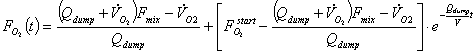
 Eq. E
Eq. E
The nominator describes the net flow of oxygen flow in the circuit and the denominator the total flow venting (i.e. leaving) the breathing circuit.
The equation E. will be used below when discussing the specifics of the DC55 gas addition system.
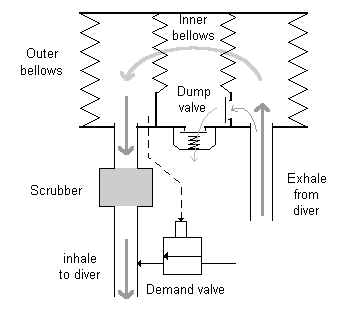
Figure 2. The simplified pneumatic diagram of the DC55.
The DC55 breathing circuit
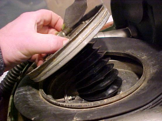
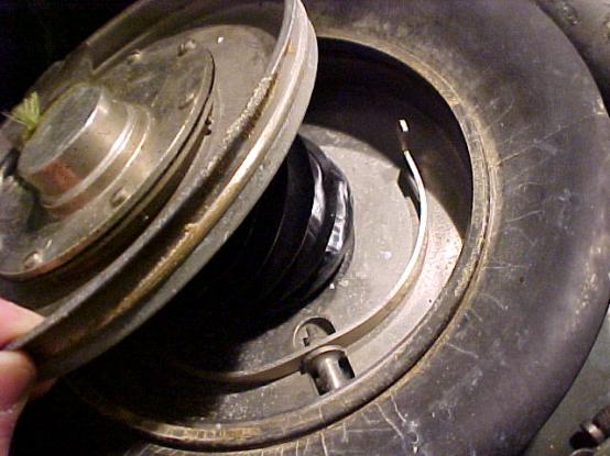
The DC55 has a back mounted bellows system that acts as the counter-lung. The bellows is not weight compensated.
Inside the main breathing bellows a smaller inner bellows is mounted co-axially.
Picture courtesy
of Divers Daves’ page http://www.nobubblediving.com/dc-55.htm
When the diver exhales, both bellows rise, a fraction of the exhaled gas goes through a non-return valve into the inner bellows. When the diver subsequently inhales, both bellows drop and a fraction of the breathing volume is expelled into the surrounding water through a dump valve. The inspired gas is scrubbed. When the breathing bellows drop sufficiently a demand regulator (see picture below) is activated compensating for the gas dumped to ambient.
Picture courtesy of Divers Daves’ page http://www.nobubblediving.com/dc-55.htm
The unit will work from minimum bellows volume and upwards thus the diver will note a slight increase in buoyancy when the workload (and thus the tidal volume) increase, a peculiarity shared with other demand addition units like the IDA-71 and the LAR III and LAR V.
Diver Daves’ tear down page contains more detailed pictures of the DC55, http://www.nobubblediving.com/dc-55.htm
Fresh gas addition
The fresh gas addition is made by exchanging a fixed fraction of the tidal volume with fresh gas. The ratio is not changed with depth thus in fact increasing the fresh gas addition (as measured as mass flow) with increasing depth.
Once again, the volume of fresh gas added is constant. However, since the pressure increases, the amount (i.e. number of molecules) of gas added to the breathing circuit is increased.
The resulting steady state oxygen fraction will be lowest at shallow depths and gradually get closer to the fresh gas mixture as depth increases.
DC55 fresh gas addition theory
The extraction ratio was defined above and if the minute volume is expressed as a function of extraction ratio and oxygen uptake:
![]() Eq. F
Eq. F
The gas volume dumped is related to the (expired) minute volume and ambient pressure, Pamb (see the paragraph above):
![]() Eq. G
Eq. G
Combining the two equations above yields:
![]() Eq. H
Eq. H
Where Kratio is the ratio of the volume of the inner (dump) bellows to the outer bellows. In the DC55 the inner bellow has (as measured by Diver Dave) a diameter of 75 mm and the outer a diameter of 250 mm thus the volume ratio is:
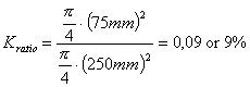 . Eq. I
Inserting into the steady state term of the SC equation:
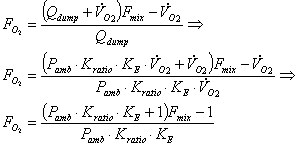 Eq. J
Eq. J
From the equation above, is apparent that the design has no dependency on the oxygen uptake and since the dosage ratio is selected before the dive the only variations left is due to the extraction ratio and the diving depth!
As stated above, when the depth increases the fraction of O2 in the circuit will approach the fresh gas fraction.
The lowest fresh gas fraction that will give a 20% oxygen fraction in the breathing circuit close to the surface is:
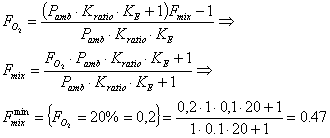 Eq. K
Eq. K
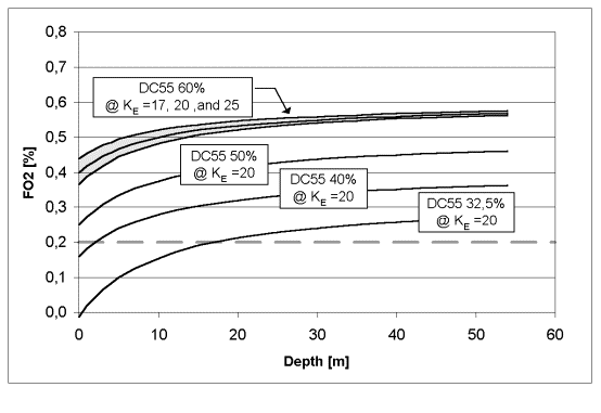
Figure 3. The variation in FO2 vs. depth for the DC55 with a volume exchange ratio of 10% and various fresh gas mixes. Note that the oxygen fraction will be lower than 21% at shallow depth for some gases.
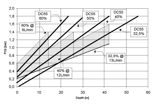
Figure 4.
The variation in PO2 vs. depth for the DC55 with a volume exchange
ratio of 10% and various fresh gas mixes. Note that the oxygen partial pressure
will be lower than 0.2 bars at shallow depth for some gases
Each of the three light gray areas in the figures above represent one of the three standard NATO mixes used for constant mass flow SCR. The upper limiting line of the shaded are is the steady state of partial pressure seen in the loop at low oxygen uptake, i.e. at rest. The lower limiting line of the shaded area represents the partial pressure (as a result of a loop FO2 of 21%) that is the result of high oxygen uptake (2 L/min).
The solid line represents the steady state partial pressure for different fresh gas mixes as a function of depth. Note that a diver with an extreme work capacity will not deplete the circuit from oxygen as can be done in the constant mass flow SCR.
Duration
The duration is workload and depth dependent just as an open system. The gas saving for the DC55 relaive to an open circuit will be the volume exchange ratio compared, in tyhis example the DC55 will 10% of the gas an open circuit will do.
In general, this design uses more gas than a constant mass flow SCR in the range 0 to 50 m.
Some Concluding Remarks
The benefit of the constant volume exchange is that the FO2 is relatively well controlled, especially at depth below 10m. The design allows a significant drop in FO2 at shallow depths and the gas fractions should be supervised.
In practice the unit ought to be dived with multiple gases to enlarge the depth range or with a constant mass flow addition that is activated at shallower depths.
The machine increases the gas consumption with depth and is thus one of the semi-closed designs with the least benefit with regards to gas savings with the exception to a unit that is dived shallow at low workload.
Last Updated 2002-07-15
All material on this website is copyright 2002 by Åke Larsson. All rights reserved.