The Draeger SM 1 unit is a self-mixing unit supplied with air and
oxygen that automatically mixes the fresh gas needed during the dive. The unit feed a constant mass flow
(i.e. not depth dependent) of oxygen
into the breathing circuit. The flow of diluent gas (in this case air) is
increased with depth thus resulting in a fresh gas flow that increases with
depth at the same time as the oxygen fraction is reduced. The result is that the
machine strives to maintain a constant partial pressure independent of depth.
The unit still shows a dependency of the divers' workload similar to the one
found in the constant mass flow semi-closed rebreather, see the CMF SCR
page.
The depth dependency of the diluent flow is still to be
investigated, the page will be updated when I have had a chance to pressurize
the system. According to Haux, Tauchtechnic, the unit has a constant O2 flow of
2 L/min and an air flow of 2.2 L/min at surface that increases (roughly) linearly
up to 4.6 L/min at 40m. The maximum operating depth of the unit is
40m.
The unit in the pictures below belong to the collection of the Swedish Historical Diving Society (see www.shdf.se)
and the author hereby expresses his gratitude for the opportunity to photograph
the unit.
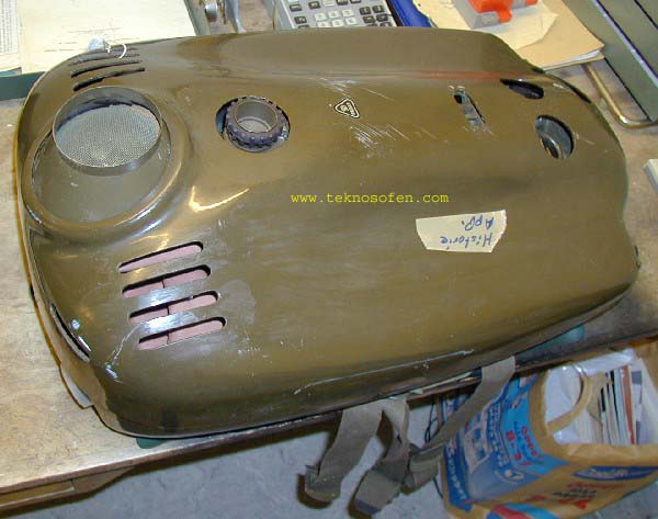 |
The Dräger SM 1 with cover on. Details from left to right:
- Bubble diffuser above the dump valve, Note the canister fill funnel that has been placed around the
diffuser.
- Battery compartment cover, the thing with a rubber ring on the top of
the unit.
- Upper lid locking mechanism
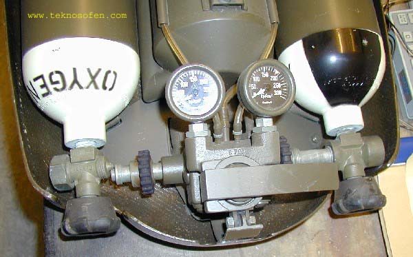
- The two pressure gauges are
(almost) visible
The two tanks valves exit the bottom of the unit but are not visible in
this picture. |
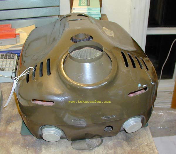 |
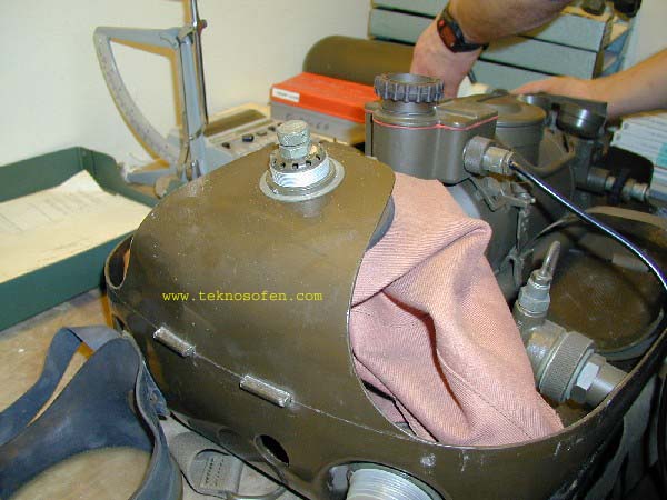
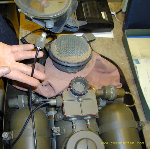
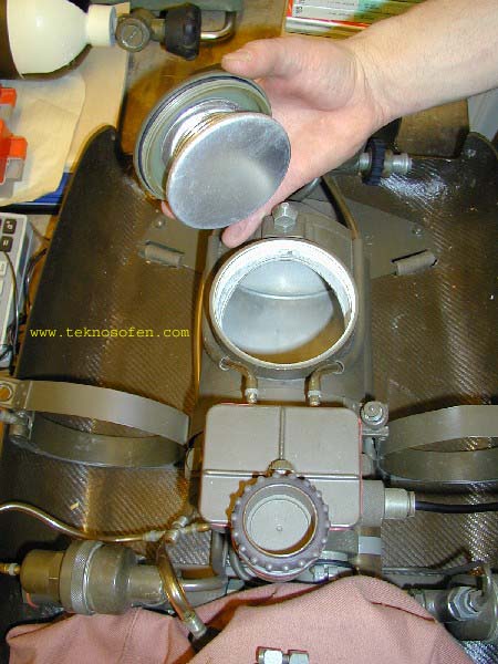
The unit seen from the top. This unit has never been dived
nor been filled with soda lime and the plastic lids protecting the
breathing hose threads are most likely the original ones. Inside the
plastic covers the metal threads are colour coded red/green.
The breathing hose threads are the same as the Norge II but the hoses
has radially sealing O-rings instead of the axially sealing rubber rings
of the Norge II.
The harness is made of soft 40mm fabric with painted aluminium
buckles,
the design of the harness and buckles is very similar to the FGG/FGT. |
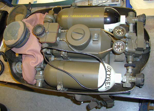 |
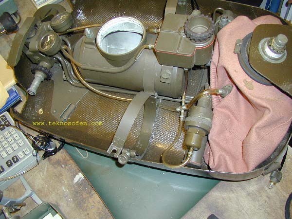
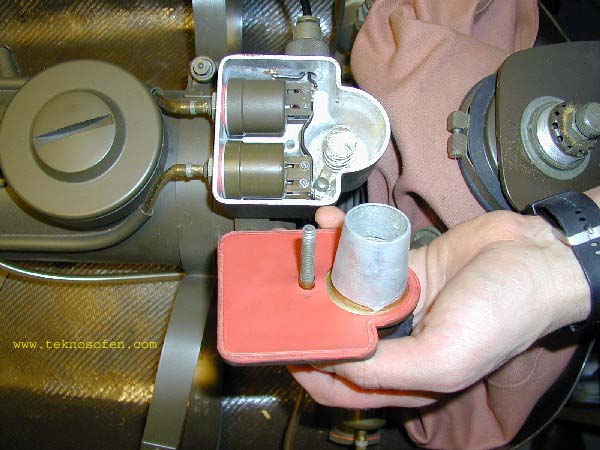
The unit without cover. From left to right
- Bubble diffuser (metal mesh with old crappy foamed rubber)
- Single breathing bag on inhalation side
- Pressure reducers (Air on top, O2 bottom)
- Battery and electronic supervisor compartment
- Scrubber canister
- Air and O2 tanks
- Pressure gauges (well hidden from the diver...)
- High pressure block with bypass lever
|
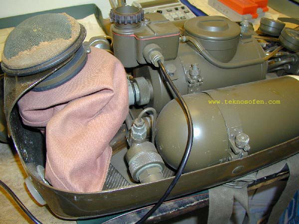 |
Side view: Bubble diffuser and exhalation bag on the O2
side. The pressure reducer looks very
similar to the one found on the Norge II and the metal tube connecting to
the top is likely to be a high pressure one. The reduced pressure is fed
back to the high pressure manifold at the bottom of the unit. This
pressure regulator is not ambient pressure referenced and has a constant
output pressure of 9 bars.
The cable exiting the battery and pressure supervisor compartment leads
to the Head Up Display, see below.
|
_side_small.jpg) |
Detail of the inhalation side with the exhalation flow path
visible. |
 |
The connection block/manifold with high pressure outlets
(the thin tubes) to the
secondary pressure reducers. The reduced pressure is fed back to this
manifold (through the thicker tubes) where the flow restricting orifices
for air and O2 are found as well as the
bypass lever. The resulting fresh gas flow is fed to the inhalation bag through
the lower transparent tube. Two low pressure tubes, the upper
transparent tubes feed pressure to the pressure supervisor.
The function of the by pass lever is presently unclear, either is
activates two valves with their own flow restricting orifices or it moves
the ordinary orifices like the Norge II
|
 |
The over pressure dump valve without the bubble diffuser.
The dump valve design is very similar to the one found in the Norge II (for details
see the service manual on the Norge page) but
an adjustment knob with locking nut has been added. |
 |
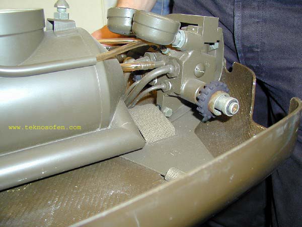
High pressure connection block with bypass lever. The
plastic tubes to the right and left feed pressure to the pressure
supervising box, see below, the mid one feed fresh gas as well as bypass gas to the inhalation
bag. |
 |
The air side of the unit. The transparent tubing feeding
fresh gas and bypass flow is split in a
cross seen close to the air diluent regulator, the four connector are as follows:
- from the left comes fresh gas as well as bypass gas
- the top feed the ambient pressure gas into the pressure supervising
box,
- To the right gas is fed into the breathing bag
- downward ambient pressure is fed to the pressure reference side of
the air/diluent regulator thus increasing the air/diluent flow
with increasing depth.
|
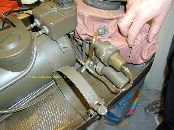 |
Close up of the air/diluent pressure regulator and
its interconnections
The air/diluent regulator is supplied with high pressure gas from the
high pressure manifold, the reduced pressure if fed back to the manifold
and its flow restricting orifice and bypass mechanism.
The air diluent regulator is ambient pressure referenced and the
output pressure increases with depth and thus the fresh gas oxygen
fraction decreased with depth at the same time as the total fresh gas flow
increases. The pressure reduces is a two stage design with an output
pressure 0.5 bars above ambient.
The chamber below the air regulator is the second stage of the pressure
reducer. the first (i.e. upper) regulator is likely identical to the O2
one with an output pressure (in this case) 9 bar over ambient.
|
 |
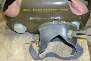
The HUD is a lamp mounted in the divers' mask that is lit
when the pressure of any of the two gases fall below a certain threshold. |
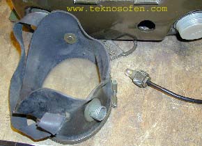 |
More details of the mask and HUD. |
 |
The internals of the pressure supervision compartment. The
pressure switches are seen to the right and the battery is mounted to the
right.
The HUD light is lit when either of the two pressures fall.
|
 |
The scrubber canister has a threaded cover with a spring loaded pressure plate. A funnel (see pictures #1
and #2 above) is used to simplify the filling. The canister is made of
thin (dural?) aluminium. the volume is ca 2L. |
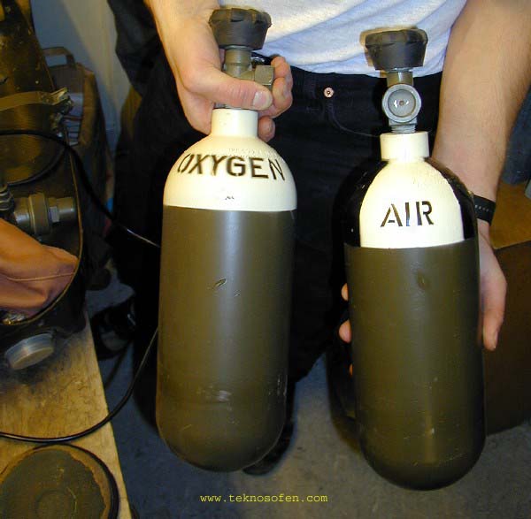 |
The volume of the aluminium tanks are 1.5 L, max pressure
200bar. These tanks
were
manufactured in 1964 |