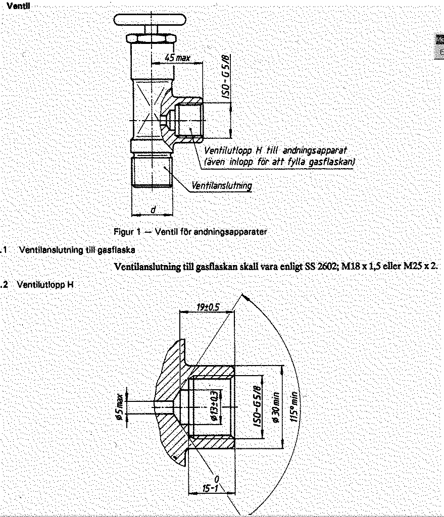
The thread is an ISO 228-1 R5/8 pipe thread.
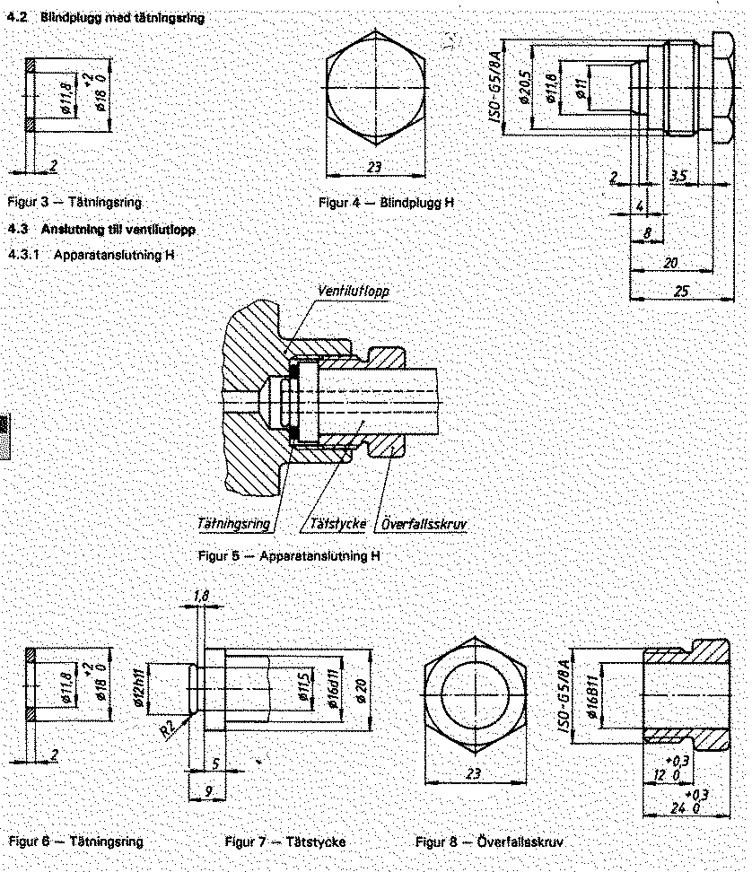
The thread is the R5/8.
In general, an O-ring 11.3*2.4 mm (same as shown for the 300 bar below) is used instead of the sealing washer indicate din the picture.
Some Swedish:
Blindplugg = "Blinding plug"
Tätningsring ="sealing ring"
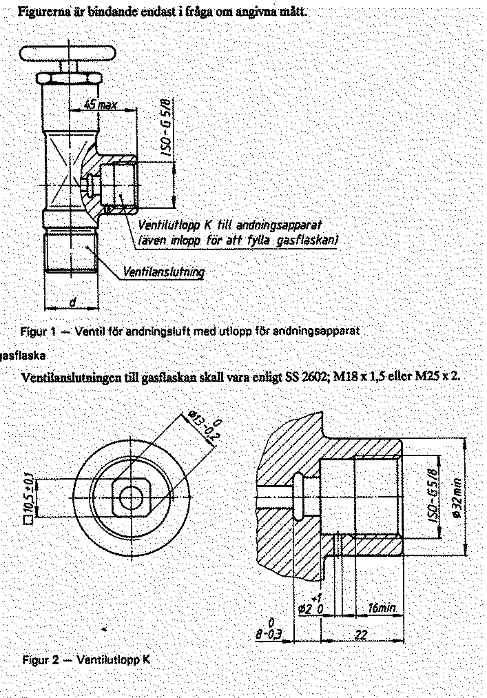
The Thread is an ISO 228-1 R5/8 pipe thread.
(the sentence about "Ventilanslutningen skall vara..." relates to the valve to tank thread that shall be M18*1,5 or M25*2.)
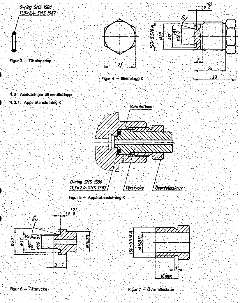
The thread is the R5/8.
The O-ring shall be 11.3*2.4mm
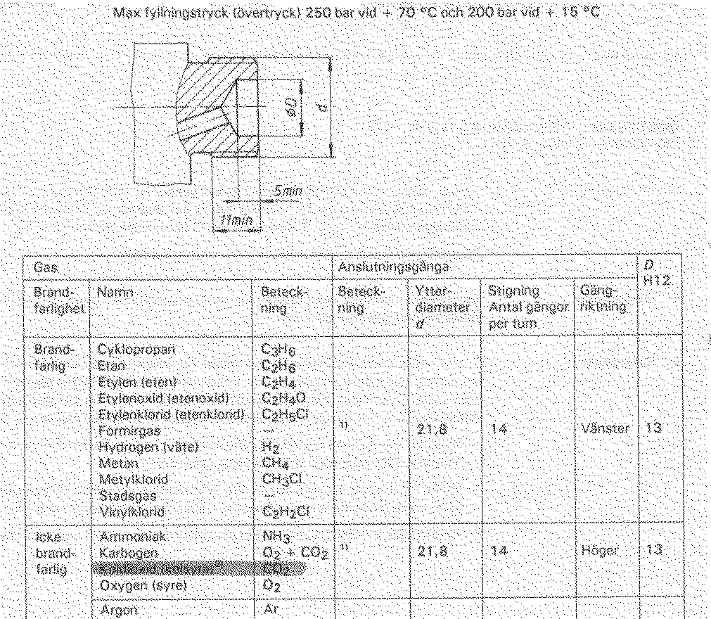
The outer diameter (d) shall be a Whitworth 21.8 mm 14 threads per inch,
right handed.
The inner diameter (0D) shall be 13 mm
Some Swedish:
Namn = "Name"
Beteckning = "abbreviation"
Ytter-diameter = "Outer diameter"
Stigning, antal gängor per tum = "# threads / inch"
Gäng riktning = "direction of the threads"
Vänster = "Left"
Höger = "Right"